I made an e-ink based, solar powered version of the famous Conways Game of Life.
Typically these celular automations run at whatever speed our eyes find to be visually pleasing but I wanted to see what a version that reflected the real worlds energy patterns would be like.
In my version the world and its cellular inhabitants must survive low power peroids each night along with reduced power peroids when its rainy or snowy. They also can only reproduce with any regularity in the brightest parts of a summers day reflecting our own worlds patterns.
The device hangs on a wall a few feet from the window. Around 9am on bright summer days I will see the first new generation being born for the day. By that time the small drawdown from the ultra low power core of the esp32 will have been replenished by the solar panel and the battery voltage will have recovered to 3.3v.
Each time that happens the ULP will wake up the main core to calculate the next generation based on the previous one which is stored in RTC memory. Then it will turn on the display driver board and push the next set of pixels to be drawn before writing this new generation to memory and entering deep sleep again.
On bright days I’ll see almost a thousand such refreshes but on a rainy day I might see less then ten and if we have a rainy week I might not see any at all. As long as battery voltage can stay above the esp32’s minimum 2.6v the ULP will keep waiting and watching and the cells will live on, waiting for another chance to reproduce when the conditions improve. Of course if they don’t the entire world will die (at ~2.6v) and I’ll have to manually restart my universe.
Development
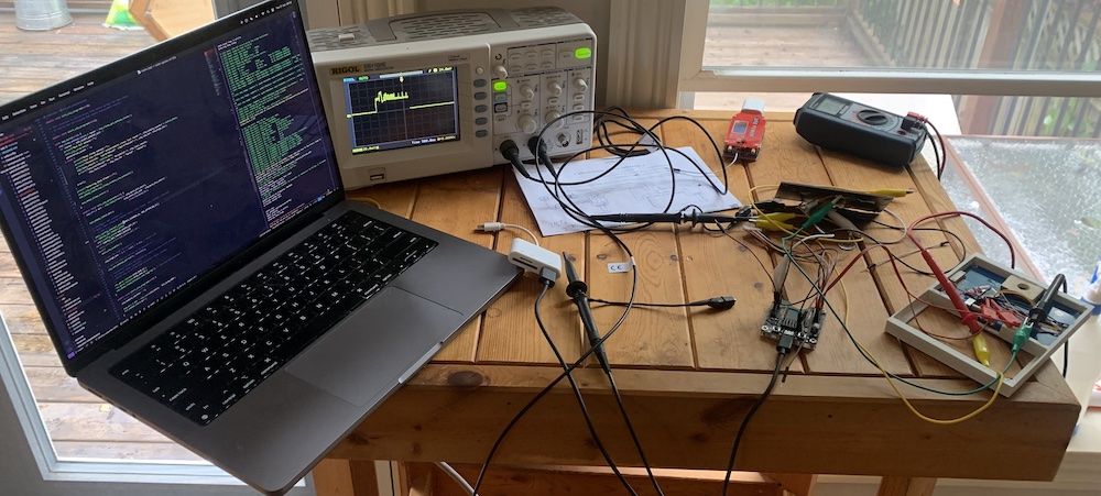
I started this project a couple years ago and since the first portion of the project involved mosty coding it went very well. Using a dev board I had the unit running off of battery in a few days and I was quite happy. I then needed a board with an efficient LDO so that I could get the power usage of the esp32’s ULP down to near the advertised 10µA. At this point I decided to take the leap away from devboards and get my hands dirty with a bare module.
This is where things slowed down. When the boards came I realized that they had castellated edges which looked impossible to solder to. Also I couldn’t get the boards to flash b/c I hadn’t used flexy pins before and I didn’t push the board in all the way. My enthusiams for the project deminished and it got shelved for over a year.
Luckily the hackaday podcast started talking about how soldering to castellated edges was possible by hand and that gave me the push I needed to dive back in.
I got the board flashing the first night and after some practice was able to get wires soldered by hand to the castellated edges on the next.
I found that the ESP couldn’t monitor voltages high enough (~3v in my testing) to give me a good operating range (above 3.3v for screen updates and 3.3-2.6v for deep sleep) so I added a low draw voltage divider based on the uPesy ESP32. s I found that using a 40f supercap for energy storage didn’t reliabily get the device through the night but also that the BMS from the vape pen lithium batteries would shut down when the screen refreshed at low voltages due to the current draw voltage dip. After playing around with capicitors I eventually settled on an unprotected lithum battery from another vape pen. This does mean that I could harm the battery drawing it down to 2.5v but I haven’t seen it go that low in actual usage and I find vape pens discarded on the street with enough regularity that I’m not too concerned.
After all the kinks were worked out I finally saw my expected energy usage patterns and had a working device.
Software
This side of things is pretty straightforward and I finally had a reason to write the standard Life impelentation. I use a bitset to compactly store the cell state since booleans each take up a byte on this artecture, which even at my fairly low cell counts is too large to fit into RTC memory.
I used the ESP-IDF for the first time because the Arduino UPC support even now seems pretty experimental (although I have used it in the past successfully) and it was a positive experence.
The ULP assembler code is mostly based off the example given in the ESP-IDF except it only looks for a upper voltage limit.
I also used the CalEPD libary to drive the e-ink display.
Code can be found in my Github.
Armageddon
In CGoL with low cell counts you can frequently run into looping situations. Typically you would check for those by keeping around some number of previous states and comparing them but I don’t have the memory to do that between deep sleeps so I just start from a random environment state every 100 frame which also keeps the display pretty full and interesting.
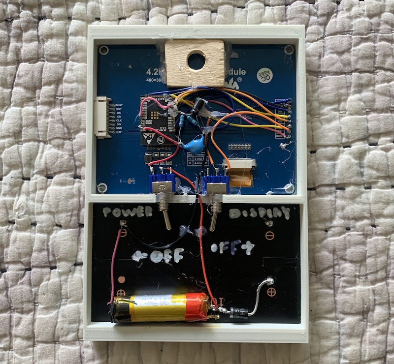 Its not pretty behind the scenes but I'm still proud my bare wires soldered to the castellated edges worked.
Coverage
You can read more about this project on adafruit and Hackaday.